describe the different components and subsystems of the robot here (from a practical perspective), including the two types of batteries and the ESP LEDs.
Robot Components and Subsystems#
Overview#
Broadly speaking, all robots we use have at least these key electrical components:
Some robots have additional sensors or actuators which are programmed via specialized subclasses of the base
Robotclass.Notable examples include the Quarterback V3 or the Center V2.
Robots capable of legally carrying the football must typically be equipped with a tackle sensor.
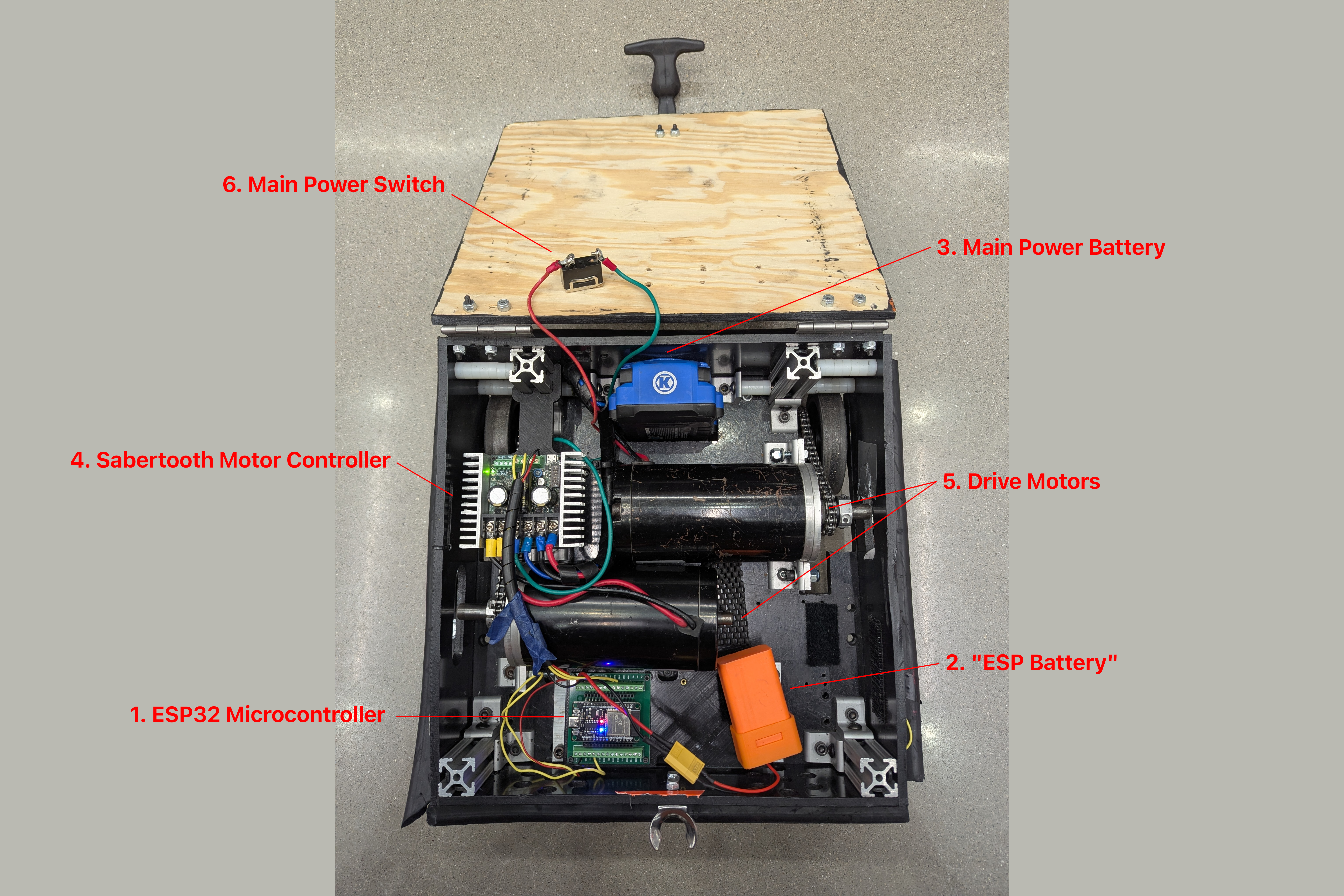
Component Diagram#
Below is an image of a standard lineman with the aforementioned electrical components marked.
Component Descriptions#
ESP32 Microcontroller#
See also
More information on this component can be found at the main article: ESP32
The ESP32 microcontroller is the “brain” of the robot and serves as the main processing hub for driver control inputs from the PS5 controller.
“ESP Battery”#
An 18650 Lithium Cell 7.7V battery pack powers the ESP32 microcontroller exclusively.
This battery is electrically separated from the rest of the robot save for any interface wires between the ESP and other electrical devices.
Note that unlike the main power battery, this does not have a switch - once plugged in, the ESP32 will turn on immediately.
Some older robots do not have this battery, and instead have the ESP32 microcontroller connected to the main power battery
Main Power Battery#
The remainder of the robot (including the drive motors and Sabertooth) are powered by the main power battery (or just “battery”).
For most robots, this is a Kobalt 24V Drill Battery.
For certain robots (the running backs or the Quarterback V3), it is be a 12V sealed lead-acid (SLA) battery.
Sabertooth Motor Controller#
The Sabertooth motor controller is what converts the PWM signal from the ESP32 microcontroller into a DC voltage sent to the motors.
This is a 24V device and runs off of the main power battery.
There are two different types of Sabertooth motor controllers: the 2x25 and the 2x32.
Drive Motors#
The drive motors are mechanically attached to the wheels of the robot, typically via a geartrain, and serve as the robot’s primary method of locomotion.
Usually these are AmpFlow motors, of which we have three types, all 24V:
“Big” - AmpFlow E30-400-24
“Small” - AmpFlow E30-150-24
“Pancake” - AmpFlow P40-350-24
Other motor types include:
Falcon 500 (12V, used in the running back
Cand the turret of the Quarterback V3)NEO Vortex (12V, used in the running back
1.21)Torquenado (12V, used in the mecanum center and V1 linemen)
Main Power Switch#
This mechanical switch controls whether the main power battery is actively supplying power to the drive motors, motor controller, and other subsystems (if applicable).
Various different types of power switches are used (from flip-switches to rotating switches). However, they are all typically clearly visible and accessible near the edge of the robot.
Notably, the Quarterback V3 has two power switches, one for the top and one for the bottom (since they are technically two separate robots).
Tackle Sensor#
Ball-carrying robots are usually required to carry a tackle sensor, which is a fancy accelerometer that triggers the lights to change to red when the robot is impacted (or, in some cases, increases rapidly in speed).
We have revision 3 and revision 4 tackle sensors.